
This ladder logic is designed to increment New_Data safely and exactly once per trigger. To fully understand why the SET and RESET are placed where they are, we must follow the actual PLC scan sequence as it happens in your program.
PLC executes logic:
Left → Right
Top → Bottom
Every scan cycle
Let’s break down the true signal flow.
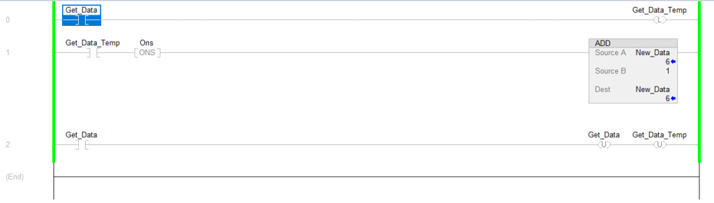
Step 1 – Trigger Condition Becomes TRUE
When the system condition activates (for example Get_Data logic), it causes Get_Data_Temp to become TRUE through the latch logic used in your program.
Get_Data_Temp is not just a normal input — it is a latched internal control bit.
This is important.
Step 2 – One Shot (ONS) Detects Rising Edge
When Get_Data_Temp transitions from FALSE to TRUE:
The ONS instruction becomes TRUE for one scan only.
This converts a continuous signal into a single event pulse.
Without ONS, the ADD instruction would execute on every scan while the bit remains TRUE.
Step 3 – ADD Instruction Executes
Because ONS is TRUE for one scan:
New_Data = New_Data + 1
The increment happens exactly once.
This is the main operation of the rung.
Step 4 – SET Instruction Latches the Bit
After the ADD instruction executes, the SET (OTL) instruction latches Get_Data_Temp.
Why is this placed at the end?
Because PLC evaluates the rung left to right.
We want the ADD to complete before the latch state is confirmed.
Placing SET at the end ensures:
- The increment operation is not interrupted
- The event is stored properly
- The logic remains stable through the scan
The latch acts as controlled memory.
Step 5 – RESET in the Next Rung Clears the Cycle
In the following rung, the RESET (OTU) instruction clears:
Get_DataGet_Data_Temp
This happens only after the ADD operation is fully completed.
If RESET were placed earlier:
- The trigger could clear in the same scan
- The ADD might not execute reliably
- The logic could become scan-dependent
By resetting in the next rung, we guarantee a full clean cycle.
Why This Design Is Important
This exact pattern ensures:
- One increment per trigger
- No multiple executions
- No missed triggers
- Stable and repeatable logic
- Scan-independent operation
What Would Happen Without This Structure?
Without proper SET and RESET placement:
- Value may increment multiple times
- Or may not increment at all
- System becomes unpredictable
- Debugging becomes difficult
Industrial Relevance
This exact structure is used in:
- Part counting systems
- Barcode indexing
- Batch numbering
- Production data logging
- Recipe ID generation
It is considered a professional PLC programming practice in Rockwell systems.
Final Conclusion
In this program, SET is placed at the end to confirm and hold the event after execution, and RESET is placed in the next rung to safely prepare for the next trigger cycle.
This sequencing guarantees reliable, deterministic, and industrial-grade operation.
Understanding this concept separates beginner PLC programming from professional automation engineering.